Microetching appears different under different angles of illumination and viewing. This gives an animated effect when one walks past it. However, a similar animated effect can occur if the viewer is stationary, but the light source illuminating the piece appears to move. Every moving part eventually wears out, so rather than moving the light, we built an array of lights that turn on and off in sequence, giving the appearance of movement. We call this a Lightbar.

The first Light Bar was designed to function at the Franklin Institute in Philadelphia. Like concert lighting, it was not intended to be pretty but to disappear into the blackness far above the piece. This made it relatively easy to build. We could use a lot of off-the-shelf components. Many of these were intended for stage lighting.
However, Greg and I decided that we would make another Lightbar. Very few ceilings are as tall as the space Self Reflected enjoyed in the Franklin Institute, so the new version would need to be much closer. All of the individual lights would now need to be much closer together but no less bright, and the whole Lightbar would need to be aesthetically pleasing enough to be in the same visual frame as the piece itself.
I could see several mechanisms for failure. For several weeks, at night I would lay there in my bed worried that it would mechanically collapse, get too hot and fry itself, not be bright enough, not be fast enough to produce animations, or simply be too ugly. There were a lot of ways this project could go sideways. I firmly believe in the phrase “Luck is the Residue of Design.” In engineering, you reduce risk by doing the design work. There’s no magic, just sweat.
First, I found a microcontroller and current amplifier that were designed for LED chains. This controller functions in a “whisper-down-the-lane” communication style. I designed a single LED unit cell and simulated it electrically. Electrically, it was fine, but I could also estimate the heat generated by each component. It was clear that things would get very hot, particularly if multiple LEDs were on near each other for an extended time. A typical FR4 substrate simply wasn’t thermally conductive enough. The solution was to reduce the thickness of the board and thermally mate it to a thermally conducting back. This got the heat down through the board, and then spread it out quickly. But even then, where was it spreading it out to? The whole bar is eventually going to get hot. The LEDs were going to play hot-potato with an ever-increasing pile of thermal joules.

Next was making this thermally conducting substrate. Aluminum 6061 has been my favorite material for building scientific apparatus. It is easily machined using conventional garage tools. It is lightweight but strong enough to hold a threaded hole. However, it is not easily bent. I bought some 6061 C-Channel and a manual roller. With great effort, I was able to put a bend in the 3x2x0.25 C-Channel.
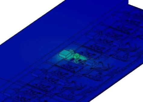
However, I did the mechanical analysis. Simply using this C-Channel by itself was potentially disastrous. It would deflect by more than 2” at its ends if unsupported. Furthermore, it was very near its own yield strength if just hung from the center point. In short, I could barely bend it, but it was quite happy to bend itself in an unhappy frown during installation.
Another challenge is making the best use of the optical power. Ideally, we want each LED to evenly spread all of its optical across the piece with as little wasted light spilling onto the walls and floors as possible. Achieving this is impossible, but in the first Lightbar, we came close putting an lens on each LED. However, now they are way too close to have individual lenses. Instead, we opted for a cylindrical fresnel film lens. For those old enough, it has the consistency of a plastic overhead projector transparency, but it bends the light along one axis as it passes through.
This was a substantial risk as well. I built a small piece of the Lighbar and illuminated the the ceiling of my garage. In parallel, I wrote POV-Ray code to simulate the structure. To my surprise, the POV-Ray code very accurately captured the throw of the light. It was so accurate in-fact, that I was able to conclude the manufacturer was using an aspheric fresnel cross-section rather than a more simply spherical one. The LEDs were also very bright and debugging them by looking at them was impossible. A welding mask became very useful.
I then set about coming up with designs.